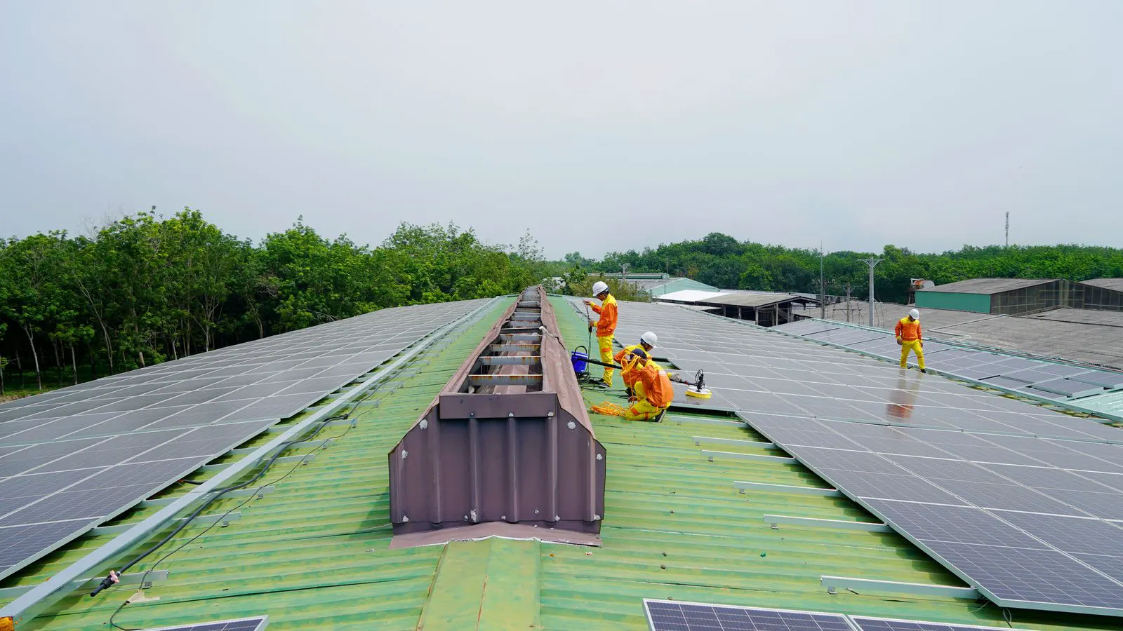
Pre-Deployment Checklist: Verifying Wind and Snow Load Data

Verify local wind and snow load data, review structural calculations, and confirm material specifications before racking installation. This checklist helps identify gaps in engineering documents and prevents costly rework on site.
- Confirm that local wind and snow load values match the specific site location and roof orientation.
- Review structural calculations to ensure they account for uplift, dead load, and live load combinations.
- Verify material certifications and fastener specifications before starting on-site assembly.
- Identify red flags such as missing load paths, unverified roof conditions, or mismatched engineering stamps.
- Keep a complete record of all documents and approvals for future maintenance and insurance purposes.
Why Verify Load Data Before Installation
Solar structural design failures usually stem from incomplete or incorrect input data rather than poor workmanship. If the wind and snow load values in the engineering package do not reflect the actual site conditions, the racking system may underperform during extreme weather events. This checklist ensures every document aligns with the physical reality of the project before a single anchor is driven.
Engineers typically provide load calculations based on local building codes and historical weather patterns. However, discrepancies can arise from outdated code versions, incorrect roof slope inputs, or assumptions about snow drift accumulation. A pre-deployment review catches these errors early, when they are cheaper to fix than after installation. Consider a flat roof project in a high-wind coastal zone. If the engineer used an old edition of the local code, the calculated base wind pressure might be significantly lower than current requirements. The racking design would appear adequate on paper, yet the anchors would lack the pull-out strength needed to resist the actual uplift forces. Identifying this gap requires comparing the code edition cited in the report against the current local municipal regulations.
Confirm Local Load Inputs
Start by comparing the load values in the structural report against the site-specific data. The primary keyword solar structural design relies on accurate wind and solar snow load figures that match the geographic location. Check that the wind speed used in the calculations corresponds to the current local code requirements. Look for the specific code edition and date in the document header. If the report cites a code version from several years prior, request a recalculation using the latest edition.
Review the wind direction assumptions as well. Wind loads are not uniform; they vary based on roof orientation and surrounding terrain. If the racking design assumes a flat roof but the site has a pitched roof, the uplift forces will differ significantly. Verify that the roof geometry in the drawings matches the physical structure. A slight discrepancy in the roof pitch, such as 15 degrees versus 18 degrees, changes the wind pressure coefficients used in the calculations.
Check the snow load calculation accounts for the correct accumulation depth and drift patterns for the region. In mountainous or hilly areas, snow drifts can accumulate at the edges of structures or behind obstructions. If the site is located in a valley or near a ridge line, the engineer must account for these localized accumulation zones. Generic snow load values often assume uniform distribution, which can be dangerous in terrain that traps snow.
Check Structural Calculations and Load Paths
The structural report must show how loads transfer from the panels through the rails, clamps, and anchors into the roof structure. Look for clear diagrams or tables that trace this load path. If the report only lists total loads without explaining how they are distributed, flag it for clarification. A complete load path diagram shows the force vectors moving from the panel clamps to the longitudinal rails, then to the transverse purlins or rafters, and finally into the roof deck and primary structural members.
Verify that the calculations include all required load combinations. A complete package should cover dead load, live load, wind load, and snow load acting together under worst-case scenarios. For example, a critical combination might involve maximum snow load plus a partial wind load, or maximum wind uplift with a reduced snow load due to wind-driven snow removal. The structural engineer must demonstrate that the racking and the roof structure can withstand these combined stresses.
Check that the roof structure itself has been evaluated for the added weight of the racking system. If the roof is aged or has hidden damage, the racking may not perform as designed. A standard commercial roof may have metal decking that is too thin to support the concentrated point loads from anchor bolts without reinforcement. The structural report should specify whether additional backing plates or purlin reinforcements are required. If the report assumes the existing roof structure is adequate without verification, request a site-specific structural assessment of the building envelope.
Review Material Specifications and Certifications
Confirm that every component in the bill of materials has the correct certifications. Racking systems must meet recognized standards for tensile strength, corrosion resistance, and fatigue life. Check that the fasteners specified in the document are rated for the expected environmental conditions. For instance, anchor bolts used in a high-humidity environment must have a corrosion rating that matches the local atmospheric conditions.
Look for evidence that the materials have been tested for the specific climate of the site. For example, if the project is in a coastal area, verify that the steel components have appropriate protective coatings. Galvanized steel is standard, but in highly corrosive marine atmospheres, engineers often specify hot-dip galvanized steel with an additional zinc coating or stainless steel fasteners. If the documentation lists generic material grades without specific test results, request detailed specifications before proceeding.
Review the specifications for the panel clamps and rail connectors. These parts experience significant cyclic loading from wind vibration. The material specifications should indicate the yield strength and ultimate tensile strength of the aluminum or steel profiles. Ensure that the finish specifications, such as anodizing or painting, are suitable for the site conditions to prevent galvanic corrosion when different metals are in contact.
Identify Red Flags in Engineering Documents
Red flags appear more often than expected in rushed projects. The following signs indicate that the solar structural design package may be incomplete or unreliable:
| Red Flag | What It Indicates | Action Required |
|---|---|---|
| Missing load path diagrams | Unclear transfer of forces to roof | Request revised drawings |
| Generic wind speed values | Data may not match local codes | Verify against current local regulations |
| No roof structural assessment | Roof may not support added weight | Commission a separate roof inspection |
| Unstamped or unsigned calculations | Engineering responsibility unclear | Obtain signed professional approval |
| Mismatched panel dimensions | Racking may not align correctly | Confirm panel size in the layout plan |
If multiple red flags appear, pause installation and request a formal engineering review. Proceeding with incomplete data can lead to structural failures, voided warranties, and significant safety risks. For example, a missing load path diagram might mean the engineer did not verify that the roof purlins can handle the point loads from the racking. This oversight could lead to purlin deflection or failure under wind uplift.
Coordinate with On-Site Conditions
The engineering report is only as good as the site it describes. Before installation, walk the roof and compare physical conditions with the document assumptions. Check roof slope, material type, and existing fastener locations. If the actual roof differs from the design, the load calculations may need adjustment. Measure the roof slope with a inclinometer and compare it to the angle specified in the drawings. A difference of even a few degrees can alter the wind load calculations for a low-slope roof.
Pay attention to roof penetrations and drainage paths. If the racking blocks water flow or interferes with existing vents, the design must account for these changes. Coordinate with the roof contractor to ensure that all penetrations are properly flashed and sealed. This step prevents leaks and protects the structural integrity of the roof. Inspect the roof surface for existing damage, such as corroded flashing or cracked membranes. The racking design must avoid placing anchors in areas where the roof deck is compromised.
Check the existing roof structure for signs of previous modifications. If the building owner added equipment or changed the roof layout after the original construction, the structural report may not reflect the current state of the roof. Verify that the anchor locations do not interfere with existing structural members or mechanical systems.
Final Sign-Off and Documentation
Keep a complete set of verified documents on site during installation. This includes the structural report, load calculations, material certificates, and the final approved layout plan. Have the engineer sign off on the as-built drawings once the racking is installed. The as-built drawings should show the final anchor locations, any field modifications, and the final panel layout.
Store digital copies of all documents in a secure location. Future maintenance, insurance claims, or system upgrades will require this information. A complete record protects the project owner and simplifies any future structural assessments. Organize the documents by category, such as structural, electrical, and warranty information. Include the material certificates for all fasteners and structural components.
Common Mistakes to Avoid
Many installation delays trace back to skipping this pre-deployment review. The most frequent errors include using outdated load data, ignoring roof orientation, and failing to verify fastener ratings. Another common mistake is assuming that a generic racking system works for all sites. Each project has unique structural and environmental requirements. For example, a racking system designed for a standard commercial building may not be suitable for a flat roof with a low-pitch membrane.
Avoid relying solely on the installer’s verbal confirmation. Written approval from the structural engineer is the standard for professional projects. If the engineering team is unavailable, request a written clarification of any ambiguous points before starting work. Do not proceed with installation if the engineering documents are missing or incomplete.
When to Request a Re-Design
Some issues cannot be resolved with minor adjustments. If the roof structure is insufficient, the snow load exceeds the racking capacity, or the wind uplift exceeds the anchor pull-out strength, a full re-design is necessary. This is costly but far cheaper than removing an installed system that has already failed. Engage a structural engineer to review the findings and provide a revised design. Ensure the new design addresses all red flags from the initial review. Only proceed with installation after the revised documents are stamped and approved.
Final Checklist Summary
Use the numbered list below as a final verification before starting work. This list covers the key points from the sections above and can be printed and taken to the site.
- Confirm local wind and snow load values match the site location.
- Verify that structural calculations include all required load combinations.
- Check that load paths are clearly documented and traceable.
- Review material certifications for corrosion resistance and tensile strength.
- Inspect the roof for physical conditions that may affect load distribution.
- Ensure all penetrations and drainage paths are accounted for in the design.
- Obtain signed engineering approval on the final as-built drawings.
- Store a complete digital record of all verified documents.
Following this checklist reduces the risk of structural failures and ensures that the solar structural design meets the demands of the site. It takes time, but the investment pays off in the long term through safety, performance, and warranty protection.
Frequently asked questions
What is the most common error found in solar structural design packages?
The most common error is using outdated or generic load values that do not match the specific site location and roof orientation. This leads to under-designed racking systems that may fail under extreme weather conditions.
How often should load calculations be re-verified?
Load calculations should be verified before every new installation or major system modification. If local building codes change or the roof structure is altered, the calculations may need updating.
Can I use a standard racking system without custom engineering?
No. Even standard racking systems require site-specific engineering to account for local wind and snow loads. A generic design may not meet the structural requirements of a specific roof or climate.
What happens if the roof structure is not evaluated?
If the roof is not evaluated, the racking system may add more weight than the roof can support. This can lead to roof sagging, leaks, or structural failure during high wind or snow events.
Do I need a separate inspection for snow-prone regions?
Yes. Snow-prone regions require careful assessment of drift accumulation and roof slope. A separate inspection ensures that the racking system can handle the expected snow load without compromising the roof structure.