Single Axis Tracker Installation: Step-by-Step Guide
A single axis tracking installation requires careful site preparation, precise leveling, and secure anchoring. This step-by-step guide walks you through the physical execution from digging to final alignment, ensuring structural integrity and optimal performance.
- Proper site grading and anchoring prevent structural failure under wind and snow loads.
- Leveling the base structure is critical for accurate panel tracking and alignment.
- Tensioning the drive system correctly avoids premature wear on motors and bearings.
- Final verification requires checking alignment, torque, and electrical connections.
- Common mistakes include uneven concrete pads, under-tensioned cables, and misaligned drive chains.
Site Preparation and Grading
The foundation of any single axis tracking installation is the ground. Before placing a single rail or post, the site must be graded to ensure flat, stable footing. Even a two-degree slope can cause uneven weight distribution across the anchor points, leading to structural stress over time. Survey the area and mark the perimeter of the installation zone. Use a laser level or string lines to establish the primary axis direction. This direction must align with the intended tracking path. In most northern hemisphere installations, the axis runs east to west. Adjust the angle based on local sun path data and wind exposure patterns.
Grade the soil to a flat plane within the installation area. Remove organic material, loose gravel, and topsoil from the anchor zones. If the soil is soft or expansive, consider importing compacted gravel or placing concrete pads. Concrete pads are standard for most commercial and utility scale installations. They provide a rigid base that resists heave, frost lift, and point loading. Mark the anchor hole locations on the pads or in the soil. The spacing between anchors follows the manufacturer specifications for the selected rail structure. Typical spacing falls between six and twelve feet, depending on rail length and wind load calculations.
Laying Out and Anchoring the Base Structure
Once the ground is prepared, lay out the base structure. For a single axis tracker, the base usually consists of two parallel rails or a single central rail with end posts. In most designs, the rails run east to west. The central axis is where the panel array rotates. Place the rails on temporary supports, such as concrete blocks or shims, at the planned anchor points. Check the level of each support. The rail line should be perfectly level along its length. A level rail prevents the array from tilting at rest, which can cause uneven wear on the drive components.
Drill the anchor holes. The depth and diameter depend on the anchor type. In concrete pads, use chemical anchors or post bases designed for high wind loads. In soil, driven piles or deep concrete footings may be required. Pour the concrete or drive the piles according to local building codes and the installer’s engineering documents. Allow the concrete to cure fully before applying any load. Do not rush this step. Curing time varies with temperature and mix, but it typically takes several days. Once cured, install the base plates or flanges onto the anchors. Torque the anchor bolts to the specified values. Use a calibrated torque wrench. Record the torque values in the installation log.
Installing the Drive System and Axle
The drive system is the mechanical heart of the tracker. It converts motor power into rotational movement of the panel array. Install the axle or central shaft according to the manufacturer’s layout. In most single axis designs, the axle runs perpendicular to the rails. It connects the array to the drive mechanism. Place the axle bearings or support structures onto the base rails. These supports must be rigid and properly aligned. Any misalignment causes bearing wear, increased noise, and reduced tracking accuracy.
Install the drive motor and transmission. The motor is typically mounted on one end of the axle. A gearbox reduces speed and increases torque. A chain or belt drives the array from the motor. For chain drives, attach the chain to the sprockets on the motor and array. Adjust the tension so the chain is tight but not overstressed. The chain should have slight sag, but no visible deflection under light load. For belt drives, use a tensioning mechanism. Set the belt tension to the manufacturer’s specification. Check the alignment of the sprockets. The chain should run straight without lateral movement. Install guards over all moving parts. This protects personnel and prevents debris from entering the mechanism.
Mounting the Panel Array
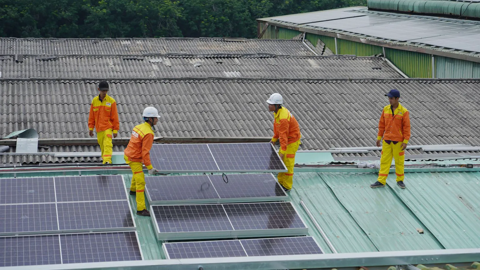
With the drive system in place, mount the solar panels onto the array frame. The array frame is a structural structure that holds the modules. Bolt the array frame to the axle or drive shaft. Use the correct fasteners and torque values. Do not over-tighten the bolts. This can warp the array or strip the threads. Once the array is secured, attach the solar panels to the array frame. Use combiner boxes or rapid disconnects as specified. The panels should be mounted with a small gap to allow for thermal expansion. Do not seal the panel edges with rigid materials. This can cause cracking during temperature changes.
Check the array balance. The center of gravity of the array should align with the axle. If the array is unevenly weighted, the tracker will struggle to rotate, especially in high wind conditions. Adjust the panel placement if necessary. For large arrays, weight distribution is critical. A few pounds of imbalance can cause significant stress on the bearings. Once the panels are mounted, inspect the connections. Ensure all panel clips, midbus connectors, and grounding lugs are secure. Clean the panels gently with a soft cloth. Remove dust and fingerprints before the system is energized.
Electrical Connections and Cable Management
Route the electrical cables from the array to the inverter and grid connection. Use conduit or cable trays to protect the cables. In a tracking system, the cables must move with the array. Use flexible cable sections or slack loops at the pivot point. This prevents cable fatigue from repeated rotation. Do not run rigid cables across the axle. They will break after a few cycles. Use UV resistant cables rated for outdoor exposure. Connect the positive and negative busbars to the inverter input. Follow the polarity markings carefully. Reversing polarity can damage the inverter and cause fire hazards.
Ground the tracker structure and the array. Bond the metal rails, array frame, and panel frames to a single ground point. Use copper grounding conductors of the size specified by the local electrical code. Connect the ground to the utility ground or a dedicated grounding electrode. Test the ground resistance. It should be low, typically below a few ohms. Insulate all live wires. Use cable clamps to secure the conductors to the structure. Avoid pinching the cables against sharp edges. Route the cables away from the moving parts. Use cable ties or clamps to prevent them from swinging into the drive mechanism.
Commissioning and Final Verification
Power on the system and run the initial commissioning tests. Check that the motor rotates the array in both directions. Observe the movement. It should be smooth and quiet. Listen for grinding, rattling, or binding. If you hear noise, stop the system and inspect the drive. Check the alignment of the sprockets or bearings. Adjust the tension if needed. Run the array through a full rotation. Verify that the end stops engage correctly. The array should stop at the programmed limits without forcing. Test the wind shutdown function. Simulate a high wind speed and confirm the array parks at the safe position.
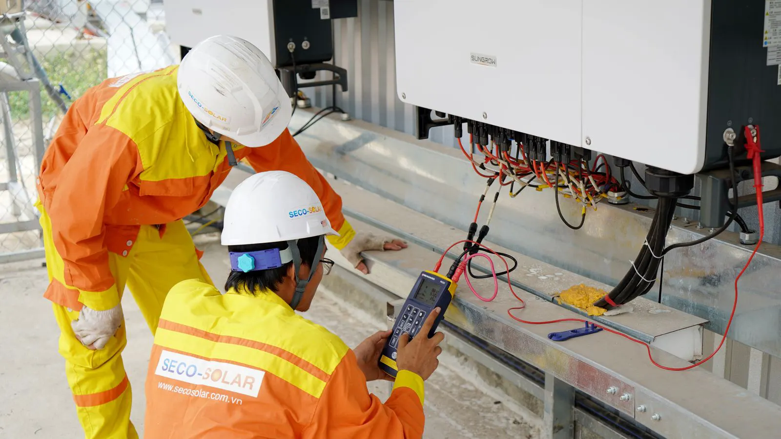
Perform a final verification of the entire installation. Check all torque values. Re-torque the anchor bolts, array bolts, and drive fasteners. Inspect the cables for damage or pinching. Verify the grounding connections. Test the inverter communication. Confirm that the monitoring software shows the array as online and tracking. Record the final alignment angle and the torque values. Store these documents in the site log. The installation is complete when all systems are secure, aligned, and operating as designed.
Common Mistakes to Avoid
Under-prepared sites are the most common cause of early failure. Uneven concrete pads or poorly compacted soil lead to anchor movement. This causes the rails to twist and the array to misalign. Avoid this by using proper grading and quality concrete. Do not skip the curing time. Rushing this step weakens the foundation.
Under-tensioned drive chains or belts are another frequent error. Loose drives slip under load. This causes tracking lag and mechanical wear. Always set the tension to the manufacturer’s specification. Re-check the tension after the first week of operation. Settlement in the base structure can loosen the alignment.
Ignoring wind loads is a serious mistake. Single axis trackers have a large surface area. They catch significant wind. If the structure is not rated for the local wind speed, it can fail in a storm. Use the engineering documents provided by the manufacturer. Do not reduce the number of anchors to save cost. The cost of replacement far exceeds the savings.
Final Checklist
Before leaving the site, complete a final walkthrough. Check the anchor torque. Check the drive alignment. Check the electrical connections. Check the ground bond. Test the motor. Test the inverter. Test the monitoring. Record all data. The system is ready for full operation when every check passes.
| Check Item | Standard Requirement | Action if Failed |
|---|---|---|
| Anchor Torque | Per manufacturer spec | Re-torque with calibrated wrench |
| Rail Level | Within 1 degree | Shim or re-pour concrete |
| Chain Tension | Per spec | Adjust tensioning bolt |
| Ground Resistance | Below code limit | Add ground rod or improve bond |
| Wind Shutdown | Verified operation | Check sensor and limit switch |
| Panel Clips | Secure and aligned | Re-tighten or replace clips |
The physical installation of a single axis tracking system is a mechanical and electrical task that demands precision. A small error in the foundation can become a large failure in the field. A small error in the drive can cause downtime. Pay attention to the details. Follow the engineering documents. Verify every step. The result is a durable system that performs reliably for years.
Frequently asked questions
How often should the drive chain tension be checked?
Check the chain tension during the initial commissioning and after the first month of operation. Re-check it quarterly. Settlement in the base can loosen the alignment over time.
What is the typical concrete curing time for anchor pads?
Curing time depends on temperature and the concrete mix. Standard mixes often require several days before full load capacity is reached. Always follow the supplier's instructions for the specific conditions.
Can solar panels be mounted directly to the rails?
No. Panels must be mounted to a dedicated array frame that attaches to the axle. Mounting them directly to the rails prevents proper rotation and causes structural stress.
What is the main cause of early tracker failure?
Poor site preparation is the leading cause. Uneven grading, insufficient anchoring, and rushed curing lead to structural movement and mechanical failure.
Do I need a permit for tracker installation?
Yes. Most jurisdictions require building and electrical permits. Check with the local authority before starting work. The permit process ensures the design meets local codes.